Final Project
What does it do?
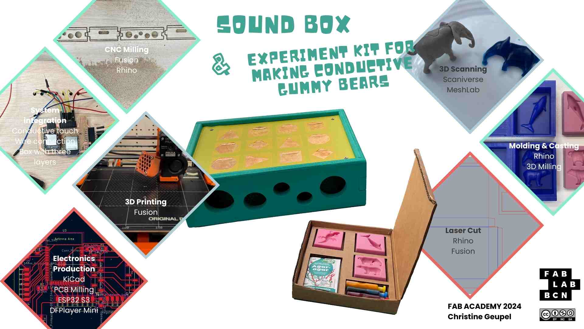
My final project is a children's toy that can be used for experimenting and playing. Additionally, I designed one accessory kit that can be used with the toy for playing or experimenting.
I designed a box that works with conductive touch and can produce sounds with various materials. Sounds can be generated by touching with fingers or by pressing other materials with the hand. The box is designed so that the sounds can be changed by uploading different sounds to an SD card.
I manufactured the box and a experiment kit to produce conductive and edible gummy animals that can generate animal sound.
Inspiration
There are some projects for children that work with conductive touch, e.g., Makey Makey, Noisy Jelly. I have always loved seeing the excitement of children when they play sounds with the Makey Makey fruit piano or generate sounds by pressing conductive paint.
Licensing
I have decided to use the Creative Commons Attribution-NonCommercial-ShareAlike 4.0 International (CC BY-NC-SA 4.0) license for my final project.

Bill of materials
Electronics
- 1x ESP32 Waroom DA €4,57
- 21x Heads Male €0,99
- 1x Resistor 10kΩ €0,09
- 1x Voltage Regulator (5v to 3.3v) €0,56
- 1x Switch €0,92
- PCB board €1,27
- 1x Power bank €2,47
- Conductive tape €3,54
- Jumper Wires € 0,96
- Speakers €6,20
- DFPlayer Mini MP3 Player €6,68
2D and 3D
- White PLA ca. €2
- Plywood 30mm ca. €5
- Plywood 150mm ca. €10
- 1,5x Wax Block €25,50
- Cartboard ca. €3
- Agar Agar €1
- Food Color €1,50
- Food Safe Silicon ca. €3
- Spray Paint ca. €4
Total ca. €83,25
What will you design?
Soundbox
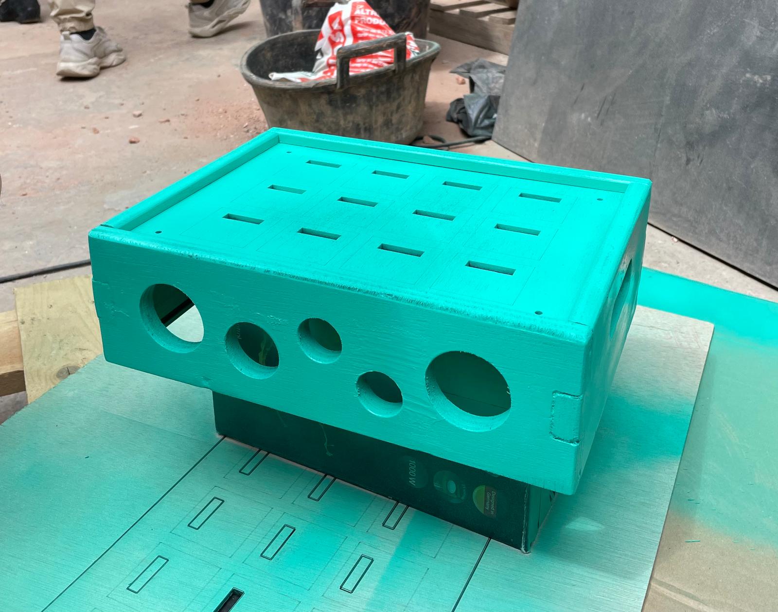
This component of the project involves a specially designed wooden box that houses the electronics for a conductive touch system. The wooden box is crafted using a combination of laser cutting and CNC milling techniques. Inside the box, the electronic components are meticulously arranged to ensure they are secure and properly integrated with the touch sensors. The box also features 3D-printed speaker grills that not only protect the speakers but also enhance the overall design and sound quality.
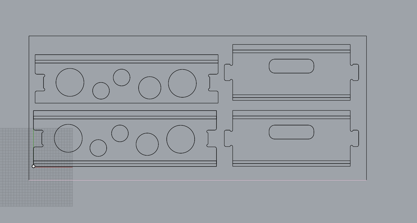
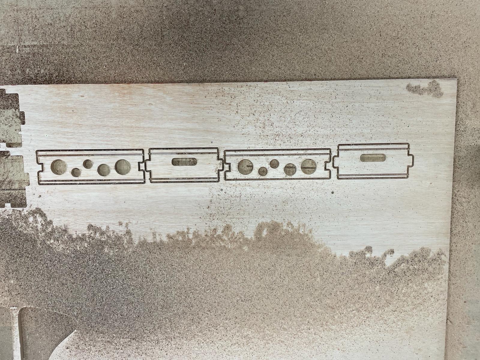
For the box, I built a wooden structure using CNC and laser cutting. The side walls are CNC cut from 15 mm plywood, and the top and bottom are laser cut from 4 mm plywood. Designed in Fusion, the side walls include holes for speakers and handles for easy transport. The walls are connected with tenon and mortise joints, and slots were milled into the side walls for the top and bottom boards. The top board is permanently integrated with slots all around, while the bottom board slides in and out for easy access. After CNC milling, the boards were sanded, assembled, and glued for stability.
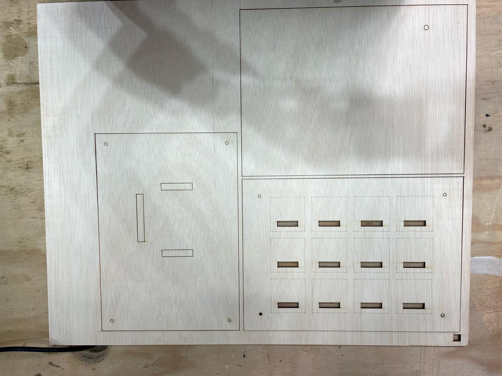
I also used Fusion to create the laser cut files for three layers and small spacer elements. The layers serve different purposes:
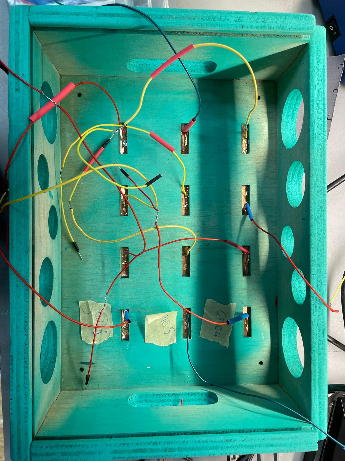
- Layer 1 - Top: Engraved for copper fields with holes for cable routing.
- Layer 2 - Middle: Holes for routing cables to the microcontroller, with space for attaching the microcontroller and speakers.
- Layer 3 - Bottom: Closes the box from below.
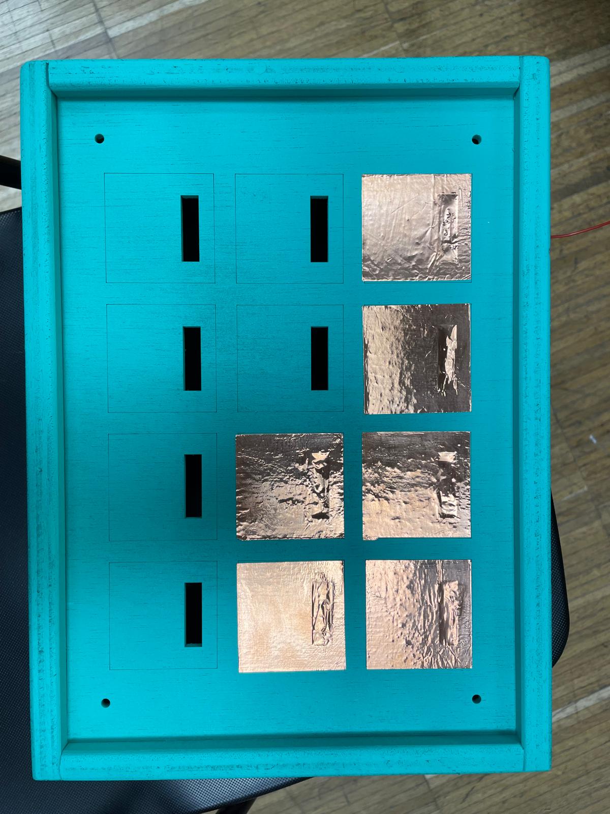
The top two layers have screw holes for connection, and spacers create a gap for cable routing between Layer 1 and Layer 2. After fitting Layer 1 into the CNC box, I painted the box for a nicer appearance.
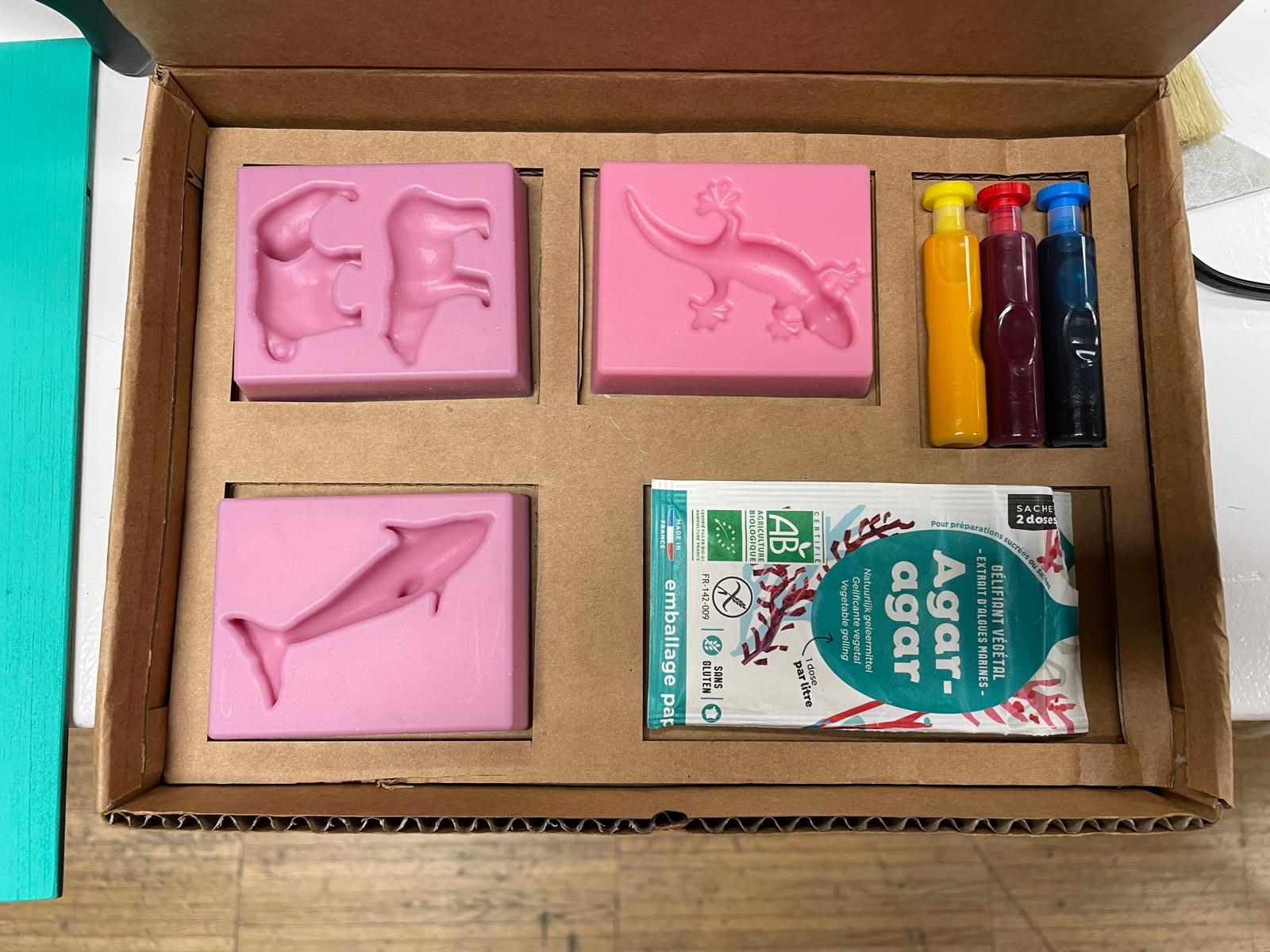
Kit for Conductive Gummy Bears
The Kit for Conductive Gummy Bears is an innovative set designed to provide users with molds and instructions to create conductive gummy animals. These molds are crafted to produce gummy bears that can conduct electricity, making them both fun and educational. The kit includes food-grade silicone molds that are easy to use and clean, ensuring safe and consistent results. This kit aims to combine creativity with scientific exploration, offering a unique hands-on learning experience.
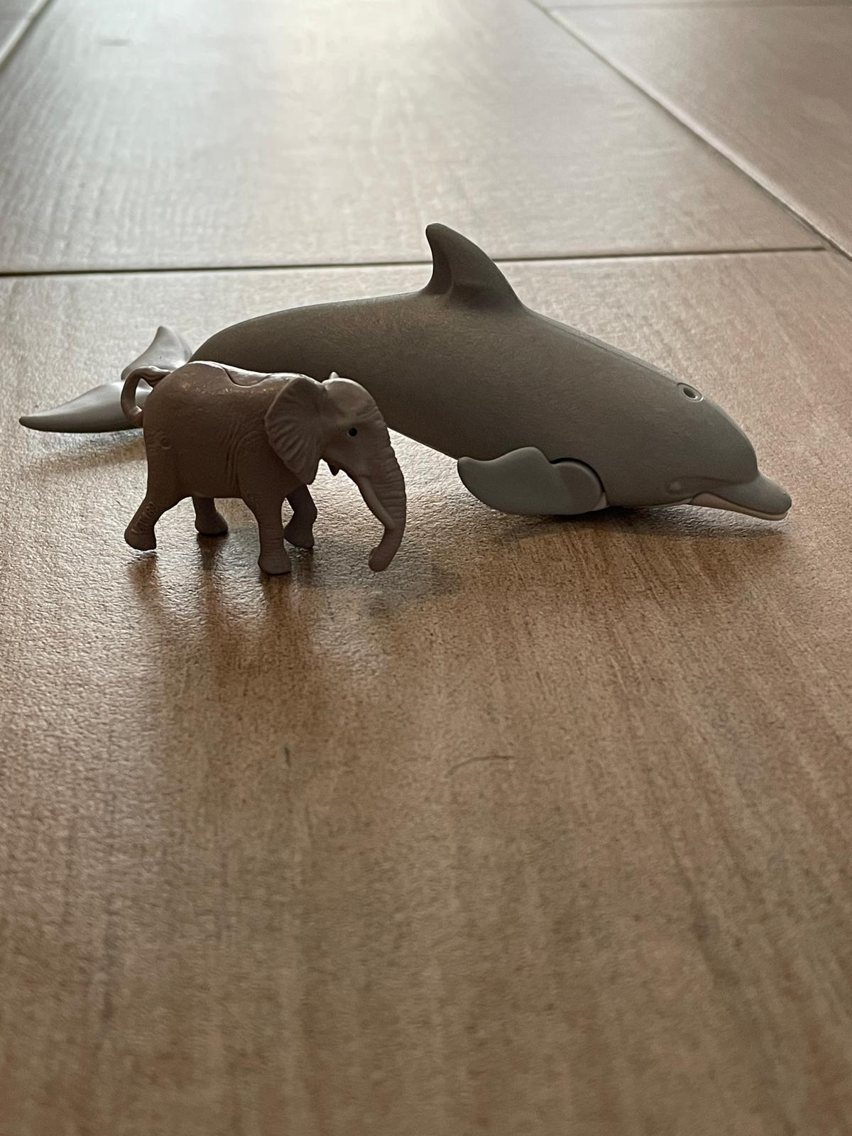
For the set, I wanted to create molds for gummy bears. With my children, I selected small toy figures—a dolphin, an elephant, and a bear—to 3D scan. The bear was too difficult to scan due to its uneven surface, so I downloaded a polar bear model instead.
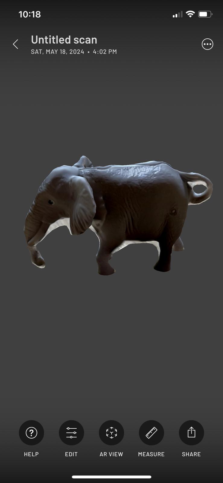
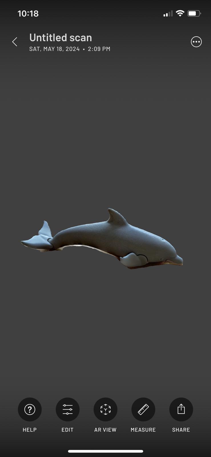
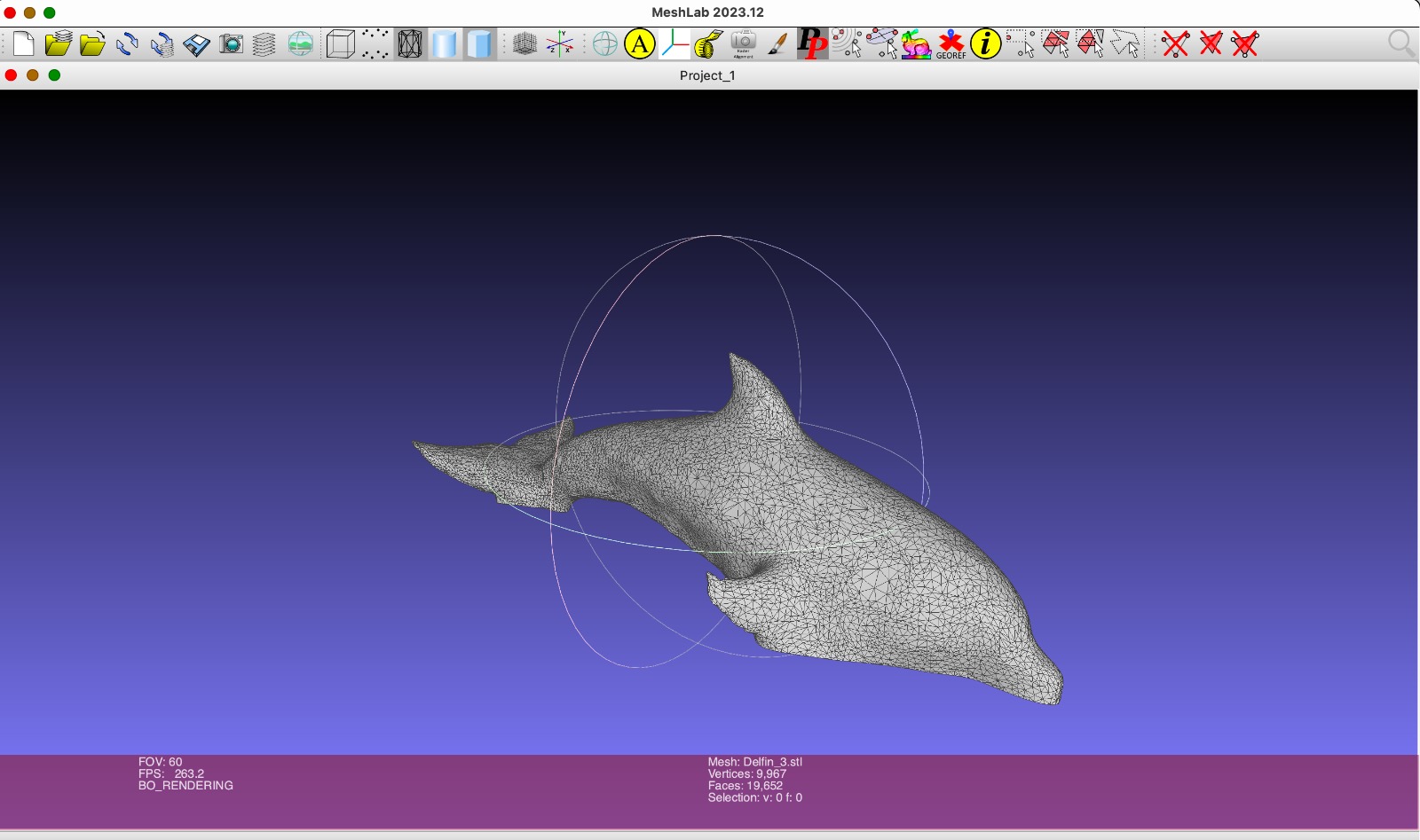
Using the Scaniverse app on my phone, I scanned the dolphin and elephant. I placed them in an accessible area, walking around them several times to capture detailed scans. This process was repeated multiple times to ensure high-quality files.
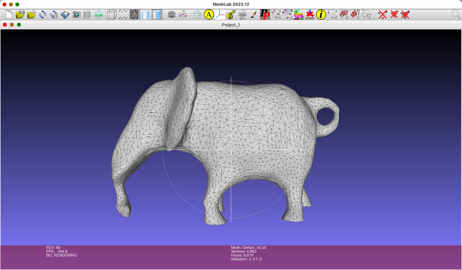
I sent the file to myself as a mesh and opened it in Rhino, but the mesh files were very uneven. To edit the meshes more easily, I installed MeshLab. Since I was unfamiliar with meshes, I used MeshLab's automatic optimization options.
I was then able to use the new files more effectively. In Week 12, Molding & Casting, I had already produced a mold. The process for creating the salamander, which I also use for the kit, can be found on Week 12 page.
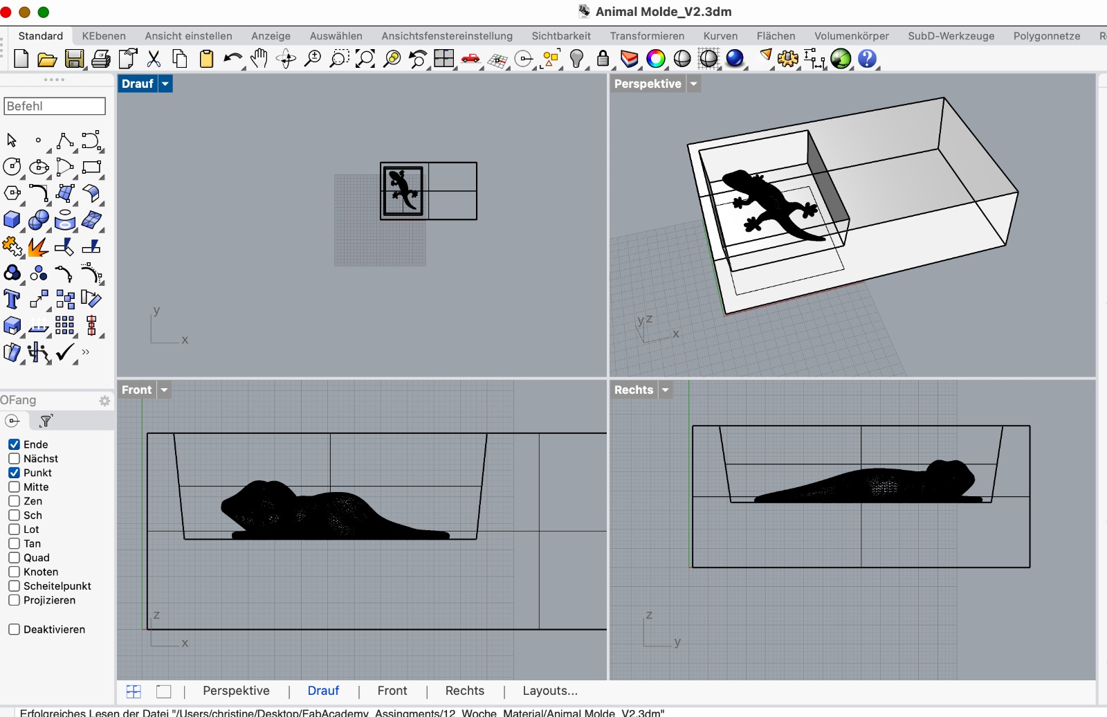
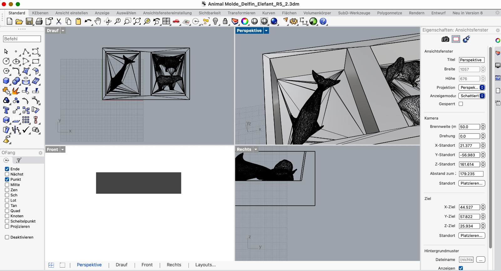
I took the animal files and replaced the figures. Then, I prepared the files in Modela. I used the same settings as in Week 12, Molding & Casting. After preparing the files, I uploaded them to the cloud and started the cut.
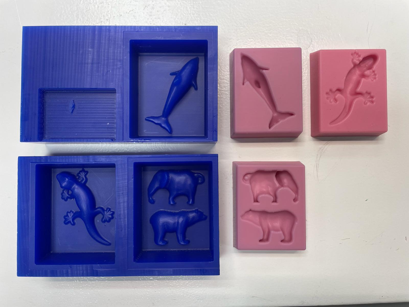
First, I prepared the machine to mill a wax block by removing the bed used for PCB milling and cleaning it with a vacuum. After inserting the drill and setting the zero point, the milling went over the edge. I realized the zero point in Modela was incorrect. After adjusting it and flipping the wax block, I restarted the cut, which then worked perfectly. The tiny elements of the elephant, bear, and dolphin were clearly visible and impressive.
Casting
To cast the mold, I chose food-safe silicone. First, I measured how much I needed by pouring water into both molds. To be safe, I mixed a bit more silicone. This was a good decision because it was just enough. I mixed the two parts, A & B, as described in Week 11. Then, I let them dry over the weekend. On Monday, I baked them in the oven for 4 hours at 100 degrees to make the molds food-safe.
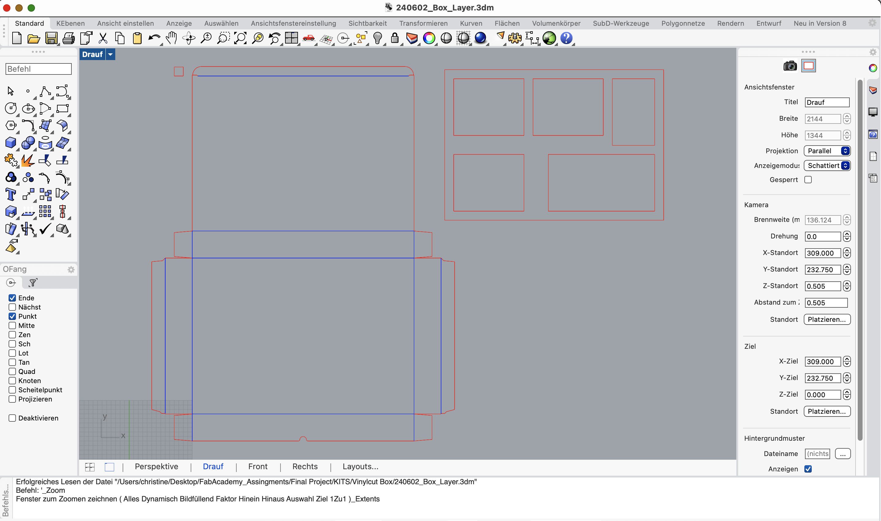
Box for experiment kit
I decided to make a cardboard box using laser cutting, aiming to neatly arrange the individual elements inside. I measured the required dimensions for the box and layers to fit the molds, agar-agar, and food coloring.
I used Template Maker to generate the box shape and downloaded the STL file for further editing. In Rhino, I adjusted the colors for cutting and engraving using the layer function. Simultaneously, I created the layer file in Fusion, exported it, and opened it in Rhino. Finally, I saved the file in Rhino 5, uploaded it to the cloud, and proceeded to the laser cutter.
As described in Week 3, I prepared the machine for cutting, loaded the material, set the zero point, and prepared the file. I first did a test cut. Since the test wasn't optimal, I slightly increased the power and reduced the speed. After another test and a good result, I started the full cut.
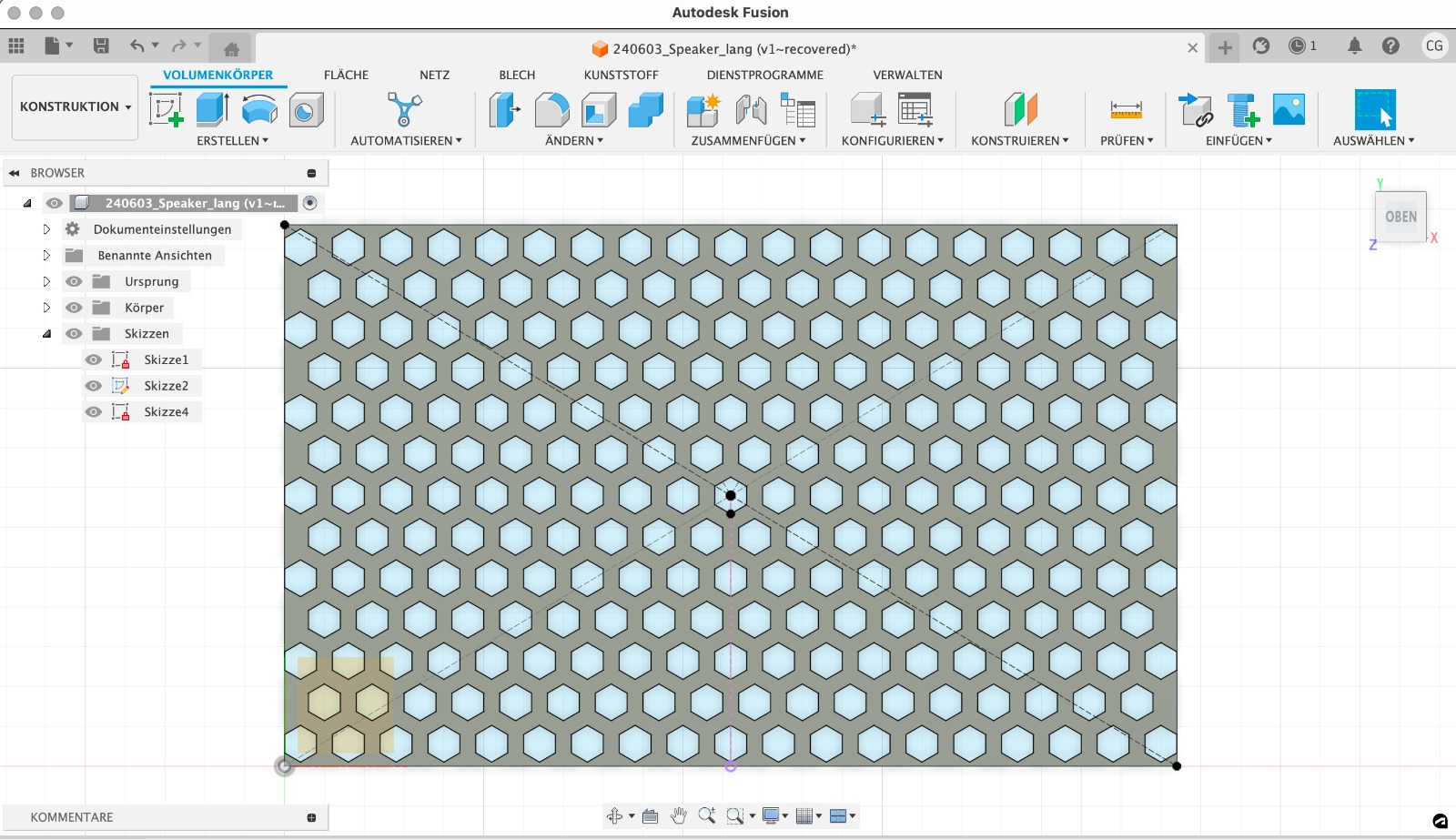
3D Printing
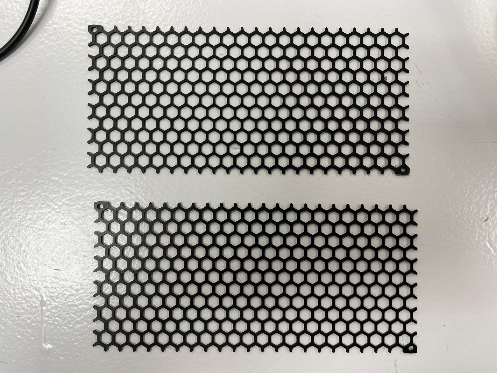
To enhance the design of the box and match the look of the speakers, I decided to 3D print speaker grills. I opted for a simple design and printed small elements, as the 3D printer bed was too small to print the plate in one piece. I designed a rectangle the size of the needed plate, extruded it to 1 mm thickness, and then added a polygon pattern across the entire element using the "Rectangular Pattern" tool. I extruded the polygons to cut through the rectangle, creating the speaker element.
Initially, I tested the print with orange flexible filament on the Bambu printer, but the results were poor. I switched to the Prusa printer, which worked perfectly, allowing me to print two elements at a time. After preparing the file, as described in Week 5, I loaded it onto the SD card and successfully printed the elements.
Electronics
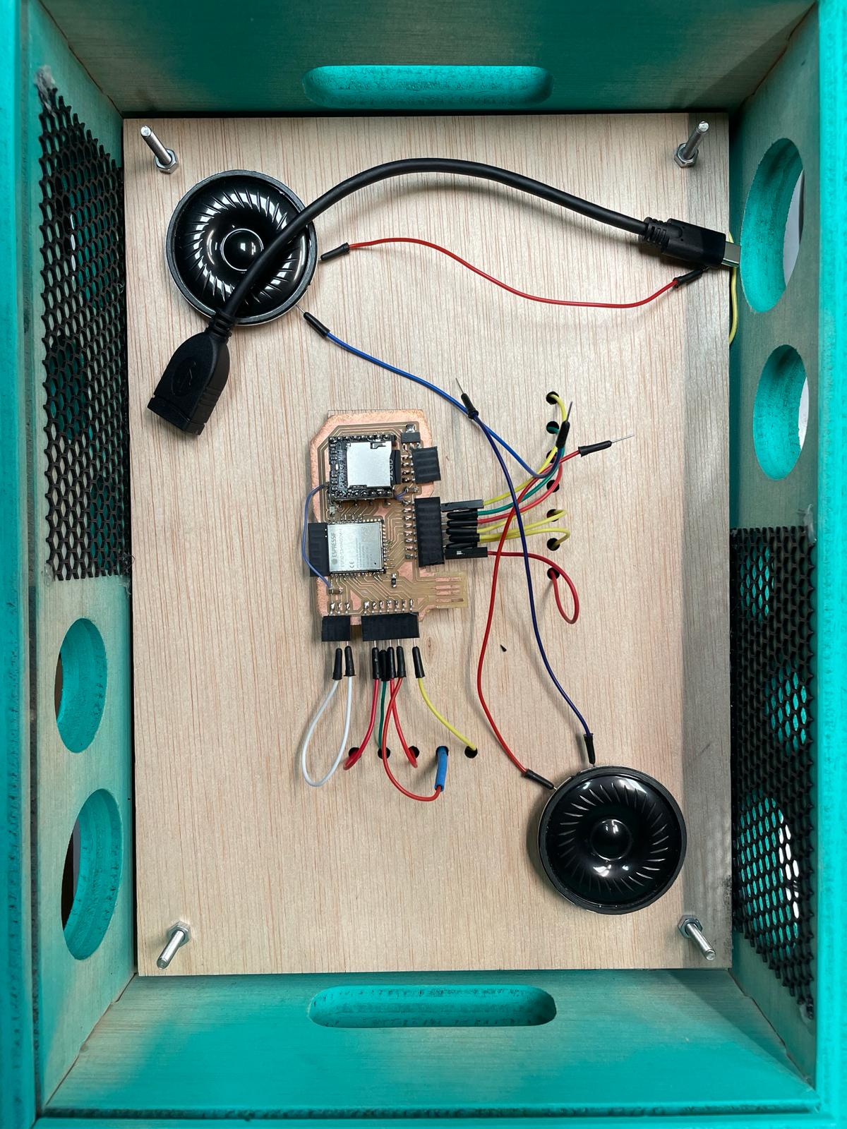
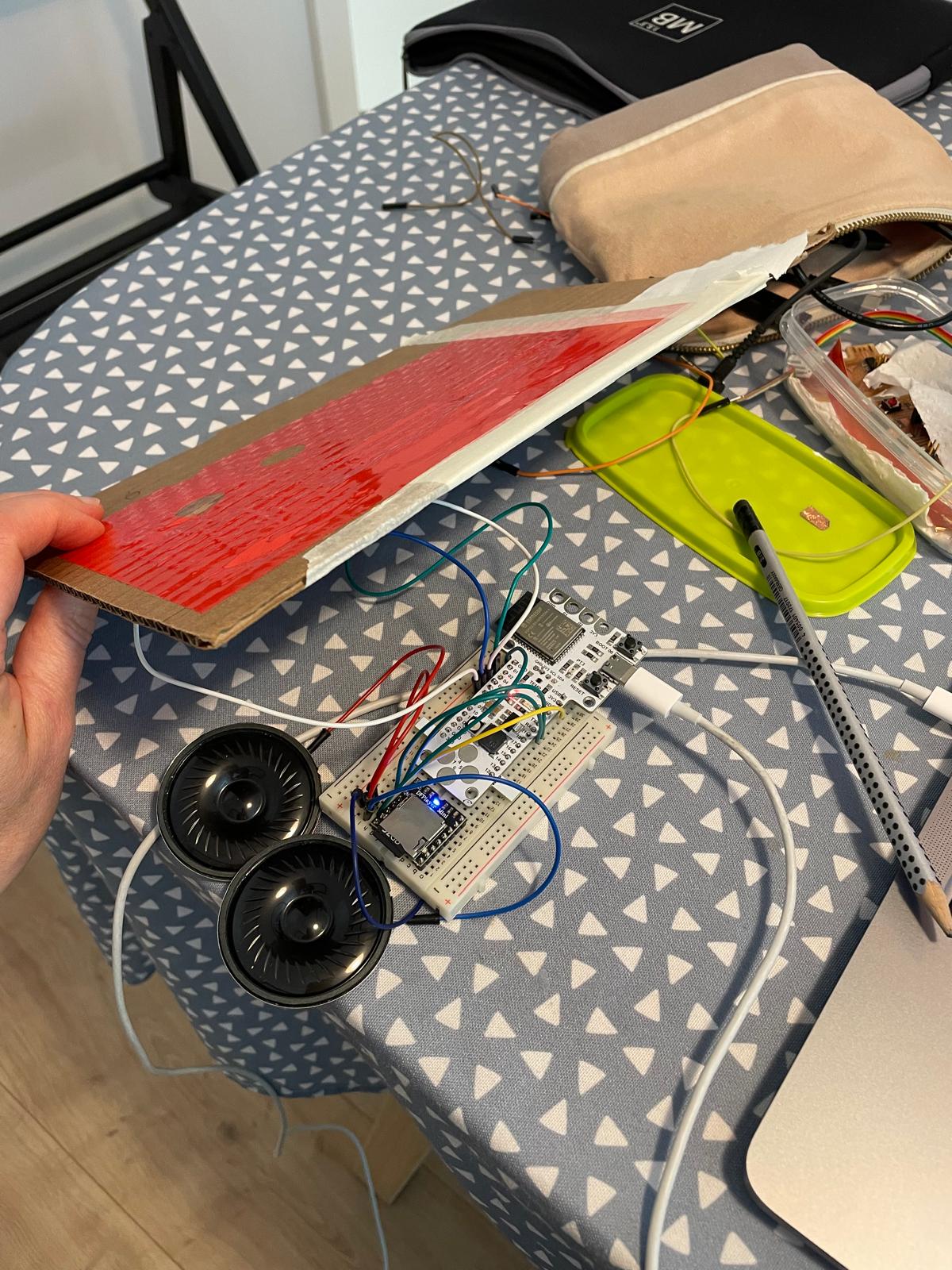
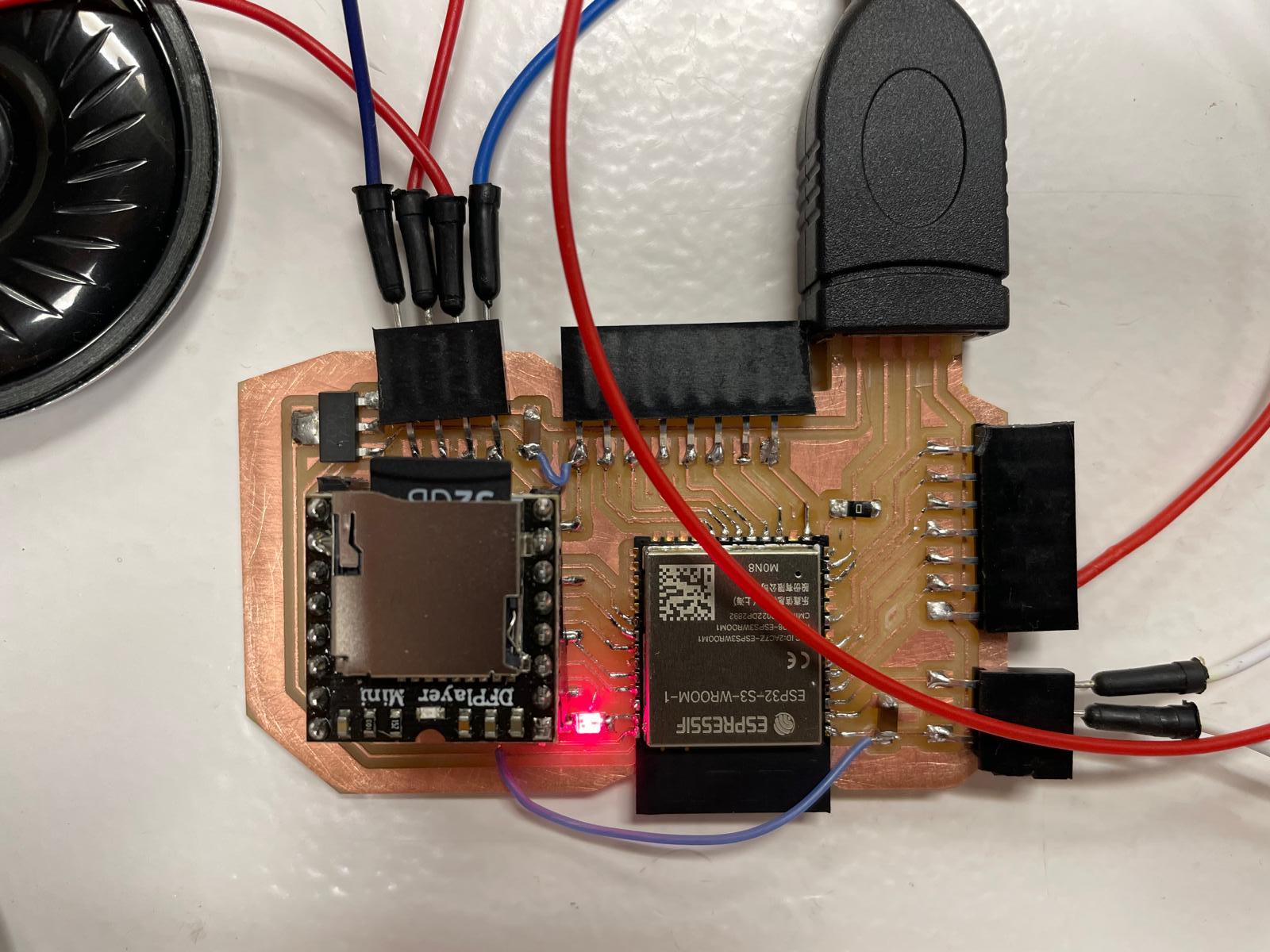
I selected the ESP32-S2-Wroom-1 to allow for many touch fields in my box and decided to integrate an SD card so children can change the sounds. The DFPlayer Mini, recommended by my tutor, connects to the microcontroller via TX RX and has an integrated SD card and speaker outputs. After successful tests with the Barduino and copper fields on cardboard, the touch board connection worked well.
To play sounds from an SD card, I connected the ESP32S3 with the DFPlayer mini. Initially, this connection was made using a breadboard, but my tutor recommended integrating the DFPlayer mini directly into the main board for better efficiency.
The following pins were used on the ESP32S3 board:
- Touch IO3 to Touch IO14
- LED
- D+
- D-
- GPIO43 TX
- GPIO44 RX
- 3V3
- EN
- IO
- GND
- Vol-
- Vol+
- Busy
Integrated components included:
- ESP32-S3-WROOM-1 module
- Voltage regulator: AMS1117-3.3
- Resistors: 10 kOhm, 330 Ohm
- Capacitors: 10 µF
- Various pin headers
- USB connector
- LED (standard 1206)
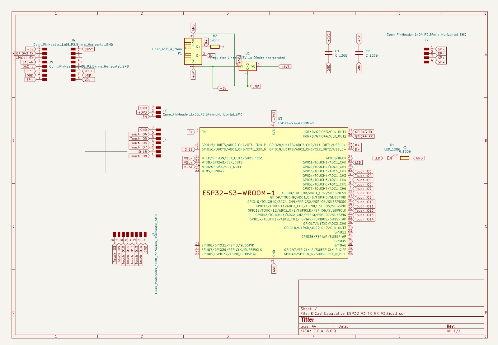
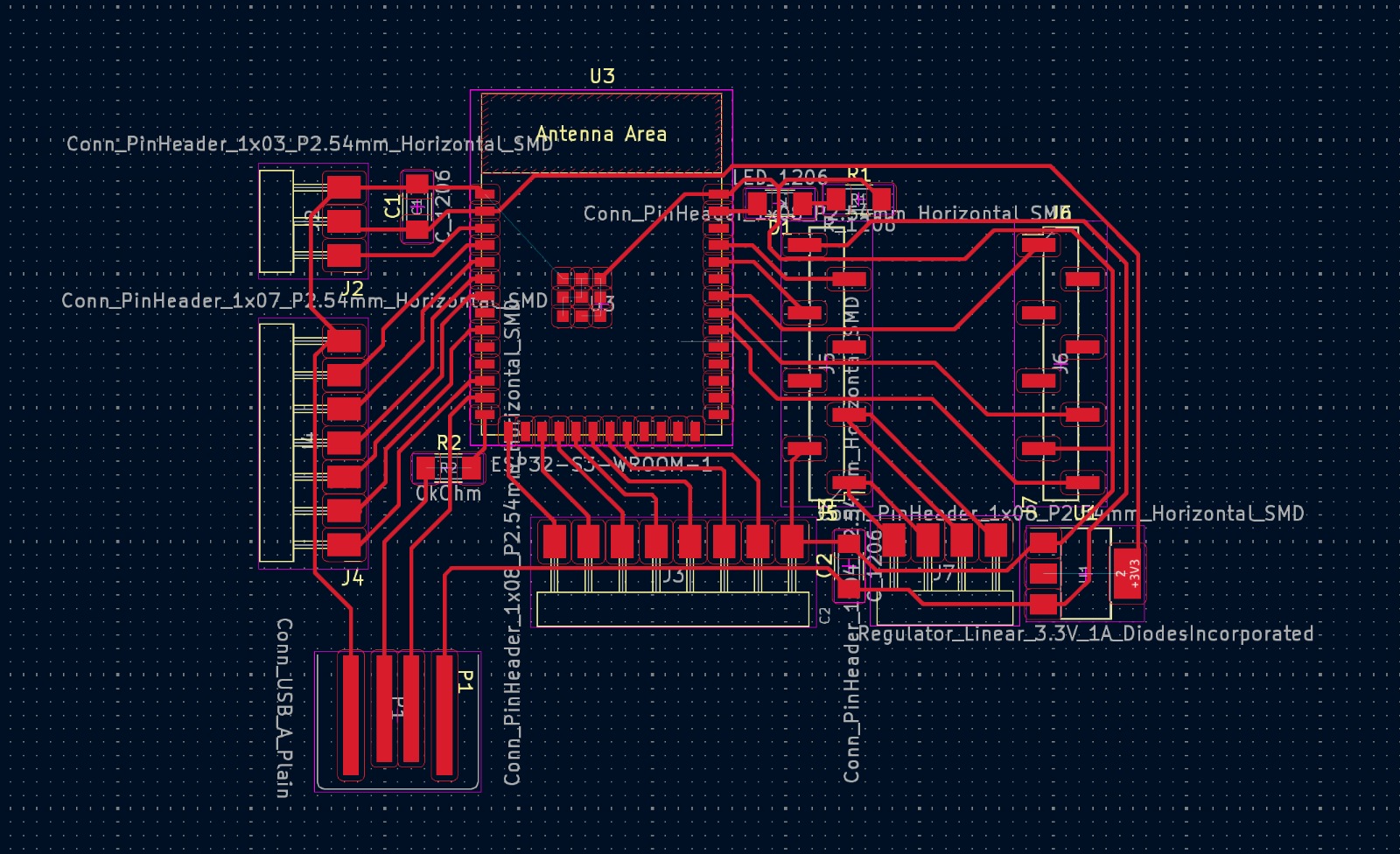
Connecting all components without crossing wires was challenging. A 0kOhm resistor was used for the USB connection. The PCB design followed the same presets from week 8 (Electronics Design) to avoid trace overlap.
- Clearance: 0.4 mm
- Track Width: 0.3 mm
- Via Size: 1.2 mm
- Via Hole: 0.8 mm
After exporting the file, I edited it in Inkscape (as in week 8). Ensuring the correct USB port size was crucial. After adjusting colors and exporting high-resolution PNGs, I prepared the files in Mods, following the process in week 4.
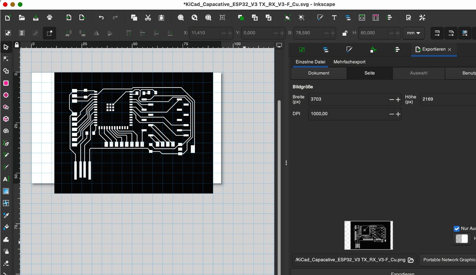
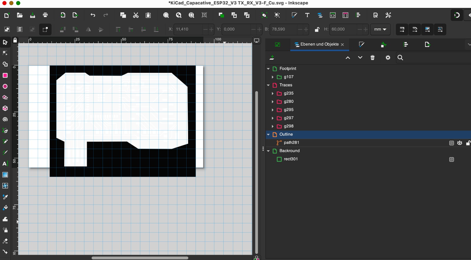
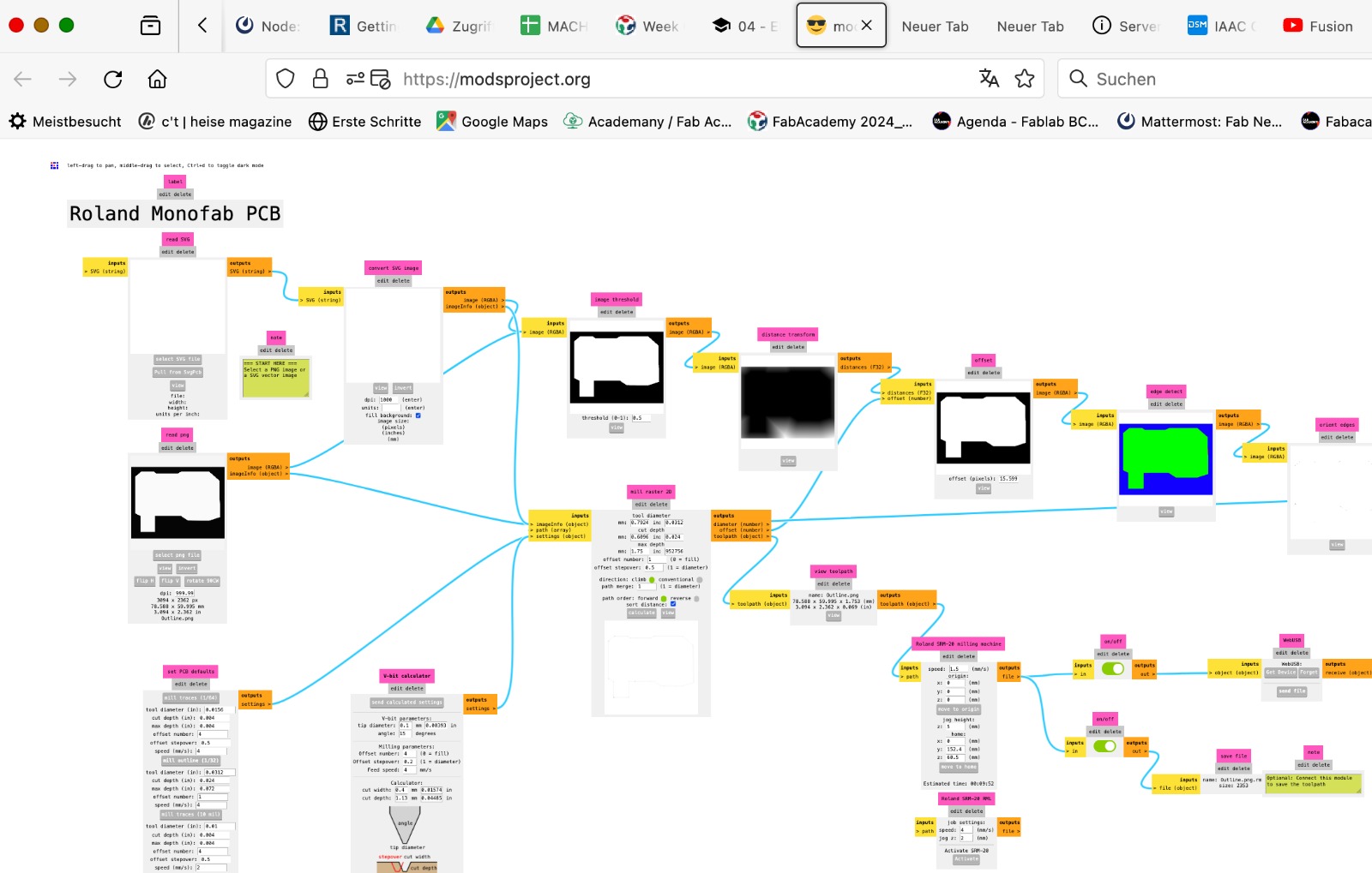
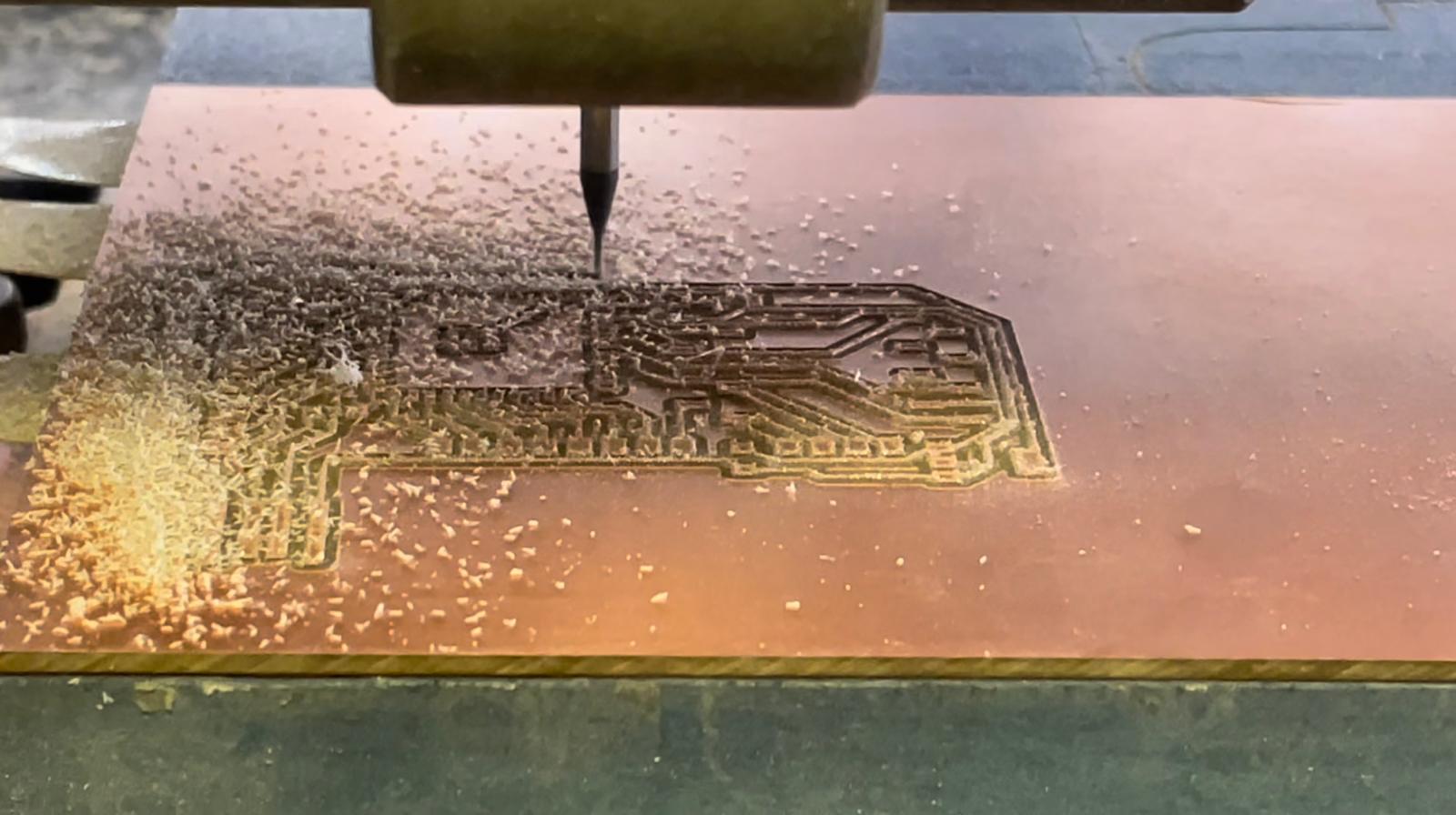
Despite my familiarity with milling, this time the drill bit broke during the trace cut. After resetting the zero point, I restarted but the milling was not deep enough. My tutor reviewed the file, found no errors, and we adjusted the y=0 point again. This time, the process completed successfully. Post-milling, I sanded the sharp edges and began soldering, which was tricky due to the small pins on the ESP32S3. With help from a classmate, I successfully completed the soldering.
The process of designing the board is also discribed in Week 8, Electronics Design.
How the copper fields and the board are connected can be read above.
Programming the sounds
To produce the sounds, I recorded nine different animal sounds from animal movies using my phone, as online mp3 files were limited and of poor quality. I converted these recordings to mp3 format, named them sequentially (1 to 9), and loaded them onto the SD card.
After preparing the SD card, I expanded a simple code previously tested with the Barduino to utilize all pins on the ESP32-S3. It was essential to test the code serially to ensure functionality and determine necessary adjustments for triggering sounds based on specific capacitance changes. A classmate suggested defining a threshold to avoid frequent adjustments, incorporating it into the code.
I used capacitive touch to generate tones based on changes in the capacitance of touch fields. Different tones are produced depending on which touch field is pressed. I structured the code serially for better control.
First, I established a TX/RX connection between the DFPlayer mini and the ESP32-S3, connecting pins 44 and 43 of the ESP32 to the TX and RX pins of the DFPlayer mini, and initialized this connection in the code. I defined touchpads 4 to 14 as Input_Pullups.
I programmed it to play the first two sounds in sequence. Touchpads 4 and 5 were set to regulate the volume, while the other touchpads were programmed to produce a tone when pressed. Using a threshold value determined through serial communication, the code is structured to detect if a touchpad is pressed and to play the corresponding tone. The output is a clear audible tone.
After that, the board had to be programmed. The programming is described in Week 9, Output Devices, and Week 11, Input Devices.
In the following two videos, you can see the output. First through serial communication and in the second video as a tone by pressing the touch fields.
What materials and components will be used?
Electronics
- 1x ESP32 Waroom DA
- 21x Heads Male
- 1x Resistor 10kΩ
- 1x Voltage Regulator (5v to 3.3v)
- 1x Switch
- PCB board
- 1x Power bank
- Conductive tape
- Jumper Wires
- Speakers
- DFPlayer Mini MP3 Player
2D and 3D
- Black PLA
- Plywood 30mm
- Plywood 150mm
- 1,5x Wax Block
- Cartboard
- Agar Agar
- Food Color
- Food Safe Silicon
- Spray Paint
- Yellow Venyl
Where will they come from?
Apart from the spray paint and a small piece of yellow vinyl, all other components were available in the lab.
What processes will be used?
- CNC cutting for the wood box
- Laser cutting for the wood box
- 3D printing for the speaker grills
- PCB cutting for the electronics
- Arduino for code to interact and communicate
- CNC cutting for wax molds
- Vinyl cutting for the paper box design
How will it be evaluated?
Functionality: The product is successful because it allows me to play individual sounds or entire tones, and it is easy to change the sounds. This means children can remove the SD card themselves, record their own sounds with an external device, and play them through the box.
Usability: The device is also successful because children enjoy using it, playing with it, and experimenting with the conductivity of materials.
What are the implications?
The project provides a fun and educational toy for children that encourages experimentation with conductive materials and sound production. It combines play with learning about conductivity and sound engineering.
This toy introduces a new way for children to interact with technology, fostering creativity and curiosity in science and engineering from an early age. It also demonstrates the practical application of conductive touch technology. There is also the potential to develop additional sets that can produce sounds with the sound box, further enhancing its educational and entertainment value.
The toy and accessory kit can be easily integrated into educational settings, such as classrooms or STEM workshops, providing hands-on learning experiences. The design also allows for easy updates and customization of sounds, keeping the toy engaging and adaptable.